How Thermal Imaging Detects Electrical Overloads
- Matt Cameron
- 10 hours ago
- 8 min read

Thermal imaging is a powerful way to identify electrical problems like overloaded circuits, loose connections, and failing components. By detecting heat patterns with infrared cameras, it helps prevent fires and system failures. Key points:
Overloads: Excess heat along conductors signals circuits carrying too much current.
Loose Connections: Isolated hot spots often indicate poor connections.
Three-Phase Systems: Uneven heating shows load imbalances or phase issues.
Verification: Findings must be confirmed with tools like ammeters.
Safety: Early detection avoids costly damage and enhances fire safety.
Thermal imaging is especially helpful for maintenance and inspections, offering a clear visual map of heat issues in electrical systems. However, it requires energized systems and additional tools for accurate diagnosis.
How Thermal Imaging Detects Electrical Overloads
Heat Signatures in Electrical Systems
Electrical systems naturally generate heat as current flows. The higher the current, the more heat is produced. When a circuit is overloaded, the current surpasses the conductor's safe capacity, creating excessive heat that spreads consistently along the conductor. Thermal cameras are designed to detect this uniform heating pattern, which often extends to related components like breakers or fuses.
What to Look for During Thermal Scans
Experienced inspectors know that a true overload is characterized by uniform heating along the entire conductor, rather than isolated hot spots . In multi-phase systems, the thermal pattern can reveal whether the entire system is under stress or if only one phase is overloaded. For example, an overloaded phase will show significantly higher temperatures compared to the others .
"A typical load heat pattern is uniform in appearance and propagates through an entire circuit." - James Brady, Level III Certified Infrared Thermographer
In three-phase systems, load imbalances stand out when one or more conductors appear noticeably warmer or cooler than the others. Additionally, issues like overheated neutral wires or transformer windings can indicate harmonic problems, even if the system seems balanced. To prevent such issues, the National Electric Code advises keeping circuit loads below 80% of the conductor's ampacity or the overcurrent device's rating.
Recognizing these patterns is essential for distinguishing overloads from other types of electrical faults.
Telling Overloads Apart from Other Electrical Faults
Thermal imaging is particularly useful for differentiating overloads from connection faults. The primary clue lies in the heat distribution. Overloads generate consistent heat across the conductor, while connection issues create isolated hot spots.
For instance, a loose connection results in a concentrated hot spot that cools quickly as heat dissipates. On the other hand, an overload causes a steady rise in temperature across the entire conductor.
One real-world example from May 2011 involved a three-phase disconnect inspected by James Brady of Brady Infrared Inspections. The A-phase fuse, rated for 75 amps, was carrying 70 amps - 93% of its capacity - while the B and C phases operated at 70% and 56% of their respective fuse capacities (100 amps and 125 amps). Thermal imaging pinpointed the issue as an overloaded A-phase fuse, not a connection problem.
Another case involved two 400-amp parallel feed conductors in an industrial setting. A thermal scan revealed a 25°F temperature increase in one conductor. Upon investigation, an ammeter showed that the "hot" wire was carrying 450 amps, while its paired "cold" wire carried less than 1 amp due to a deteriorated connection at the lug.
These examples highlight how thermal imaging helps identify the root cause of electrical issues, ensuring accurate diagnoses and proper corrective actions.
sbb-itb-3aaca89
Thermal Imaging for Electrical Safety: Prevent Fires Before They Start
The Thermal Imaging Inspection Process
Preparing for the Inspection
Before starting a thermal inspection, the system being evaluated must operate under normal conditions. This means the equipment should run at a minimum of 40% of its rated load, though anything above 70% is preferred to ensure temperature differences are noticeable. These load conditions allow inspectors to detect potential issues accurately, as the system needs to reach its usual operating temperatures.
"Equipment under inspection should be operating at a minimum of 40% of rated load, and ideally above 70%, to produce temperature differentials large enough to detect." - National Electrical Authority
Inspectors also need to calibrate their thermal cameras, adjusting emissivity settings to match the materials being scanned. This ensures temperature readings are accurate. A preliminary visual check is often done to spot obvious red flags, such as discolored insulation or warped components. Additionally, clear access to electrical panels is essential. Panel covers are usually opened during the inspection to allow direct scanning.
Once the system is properly loaded and the equipment is calibrated, the thermal imaging process moves on to scanning the electrical components.
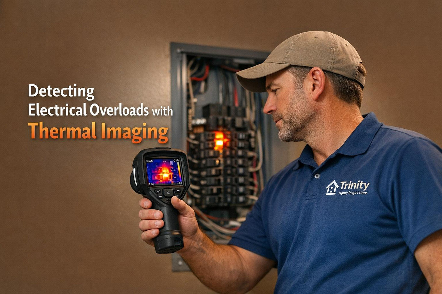
Scanning Panels, Breakers, and Wiring
Thermal cameras are used to detect infrared radiation emitted by electrical components. This radiation is translated into color-coded images, which help inspectors identify potential issues. For example, uniform heat patterns along a conductor might indicate an overload, while isolated hot spots could point to loose connections.
In three-phase systems, inspectors compare the heat levels of each phase. Uneven heating patterns often reveal load imbalances, where one phase is carrying more current than the others. Breakers and fuse blocks are also closely examined, particularly the centers, to detect centralized heat patterns that might indicate internal contact issues. Thanks to the sensitivity of infrared cameras - capable of detecting temperature differences as small as 0.1°C - problems can often be identified early, before they cause significant damage.
When potential issues are found, inspectors move on to verify their findings with additional tools.
Confirming Results with Additional Tools
Thermal anomalies that suggest overloads are confirmed using ammeters to measure current and calculate Delta-T. A true RMS sensing ammeter is particularly useful for accurate current measurements, helping inspectors determine whether a hot component is overloaded or if the issue lies in a faulty connection.
"An ammeter provides this information to the thermographer and allows the comparison of temperatures of different components under similar / identical loads." - James Brady, Level III Certified Infrared Thermographer, Brady Infrared Inspections, Inc.
Delta-T (ΔT) is calculated by measuring the temperature difference between a component and a baseline reference. This helps assess the severity of the issue. Industry standards categorize thermal anomalies into three tiers based on the temperature rise:
Class 1: 1°C–10°C increase
Class 2: 11°C–40°C increase
Class 3: Above 40°C increase
Any circuit operating near or above 80% of its rated capacity is flagged for immediate attention, as it poses risks of fire or system failure.
Benefits and Limitations of Thermal Imaging
Benefits of Using Thermal Imaging
Thermal imaging offers a non-intrusive way to detect fire hazards by pinpointing hotspots in electrical panels and wiring, making it possible to uncover hidden electrical issues behind walls.
With the integration of AI, thermal imaging systems boast over 90% accuracy in identifying electrical faults. Compared to traditional manual inspections, these systems can uncover about 30% more defects. Spotting these problems early helps avoid expensive repairs down the line.
Take this real-world example: In March 2026, a food processing facility in Melbourne faced a circuit breaker panel failure when temperatures soared to 201°F (94°C). The resulting arc flash halted production for 11 days, causing $2.1 million in losses. A quick 90-second scan with a thermal imaging camera could have identified the developing hotspot weeks before the incident.
Thermal imaging isn’t just for industrial settings - it’s also valuable for residential electrical inspections. For homebuyers, it offers clear insights into potential electrical risks, which can be used to negotiate repairs or adjust purchase prices.
Limitations to Keep in Mind
While thermal imaging has clear benefits, there are some limitations to consider. For starters, it requires systems to be energized and operating with at least 40% load to generate detectable heat. This means inspections are best performed during normal operations, not during shutdowns.
"Because an infrared imager cannot measure electrical current, suspected overloads must be confirmed with an ammeter while observing all requisite safety precautions." – Infraspection Institute
Although infrared cameras excel at detecting heat patterns, they can’t measure electrical current. To confirm suspected overloads, a true RMS sensing ammeter is needed to verify if a circuit is exceeding 80% of its capacity. Another limitation is that thermal cameras cannot see through solid objects. This means components like contacts inside circuit breakers or bus connections hidden behind metal enclosures remain out of view.
External factors can also affect the accuracy of thermal imaging. Reflective surfaces and air movement, such as wind or HVAC systems, can distort infrared readings.
Trinity Home Inspections: Thermal Imaging Experts on the Gulf Coast
Thermal Imaging Included with Every Inspection
At Trinity Home Inspections, every property inspection comes with thermal imaging at no additional cost. This advanced technology is a game-changer for electrical safety, as it pinpoints potential problems like overloaded circuits, loose connections, or aging electrical components. By using high-tech thermal cameras, inspectors can detect subtle temperature changes in panels and wiring that might otherwise go unnoticed.
All inspections are handled by InterNACHI-certified professionals, who provide same-day digital reports. These reports include thermal images that visually map out temperature variations in electrical systems. This gives clients clear, documented proof to prioritize repairs or strengthen their position in real estate negotiations. Beyond electrical safety, thermal imaging also helps spot other issues, such as moisture problems and insulation gaps, offering a more thorough property evaluation.
Serving the Alabama Gulf Coast
Trinity Home Inspections proudly serves communities across the Alabama Gulf Coast, including Daphne, Fairhope, Gulf Shores, Mobile, and surrounding areas in Baldwin, Mobile, Escambia, Washington, and Monroe Counties. As a locally owned business, they combine cutting-edge inspection tools with a deep understanding of the region’s humid, subtropical climate. This expertise is especially valuable in identifying property concerns unique to the Gulf Coast.
To ensure clients feel confident in their property decisions, Trinity Home Inspections provides follow-up support through phone, text, or in-person consultations. Whether it’s answering questions or clarifying findings, they’re committed to helping clients make well-informed choices about their investments.
Conclusion
Key Points About Thermal Imaging and Overloads
Overloaded conductors tend to show a consistent warmth along their length, making them identifiable during thermal imaging inspections. As the Infraspection Institute notes, "Statistically, overloaded circuits are the second most common cause of exceptions found during infrared inspections of electrical systems". This technology allows professionals to pinpoint these issues early, helping to prevent system failures or even fires by identifying hot spots and uniform heating patterns.
However, interpreting these findings requires professional expertise. Any suspected overload must be confirmed with a true RMS sensing ammeter. Once an overload is verified, it’s crucial to address the issue immediately, whether it involves resizing wiring or fixing faulty circuit protection. Tackling these problems early not only enhances safety but also contributes to better overall home maintenance.
Thermal imaging isn’t limited to electrical safety. It can also reveal moisture problems, gaps in insulation, and inefficiencies in HVAC systems, making it a versatile tool for diagnosing home issues. The technology is especially effective during seasons with noticeable temperature differences, as these conditions produce the clearest thermal contrasts. By identifying hidden problems before they escalate, thermal imaging becomes an essential tool for maintaining a safe and efficient home.
Why Choose Trinity Home Inspections
Trinity Home Inspections takes thermal imaging to the next level by including it at no extra charge with every inspection. This adds tremendous value for homeowners and buyers. Their InterNACHI-certified inspectors provide same-day digital reports with detailed thermal images that highlight temperature variations in electrical systems. These reports offer clear, actionable insights - perfect for prioritizing repairs or negotiating during real estate transactions.
As a locally owned company serving the Alabama Gulf Coast, Trinity Home Inspections understands the unique challenges of the region’s humid, subtropical climate. Whether you’re buying, selling, or maintaining a property in areas like Daphne, Mobile, or Gulf Shores, their team provides expert guidance and follow-up support to help you make confident decisions about your investment.
FAQs
Can thermal imaging detect if a circuit is overloaded?
Thermal imaging is a useful tool for spotting overheating electrical components and detecting potential problems such as insulation gaps or moisture. However, it cannot directly confirm whether a circuit is overloaded. Instead, it highlights temperature differences that could suggest an overload, but additional testing is necessary to pinpoint the exact cause.
What’s the difference between an overload and a loose connection on a thermal scan?
A thermal scan identifies an overload when an electrical component shows consistently high temperature readings due to excessive current flow. On the other hand, a loose connection appears as a localized hot spot or an irregular temperature pattern, which results from poor electrical contact.
When is the best time to schedule a thermal scan for accurate results?
During colder weather or when there’s a noticeable temperature difference between the inside and outside of a home, thermal scans are most effective. These conditions make it easier for thermal imaging to pinpoint hidden problems like insulation gaps or electrical overloads.