
Foundation Rebar Requirements: What The Code Actually Demands

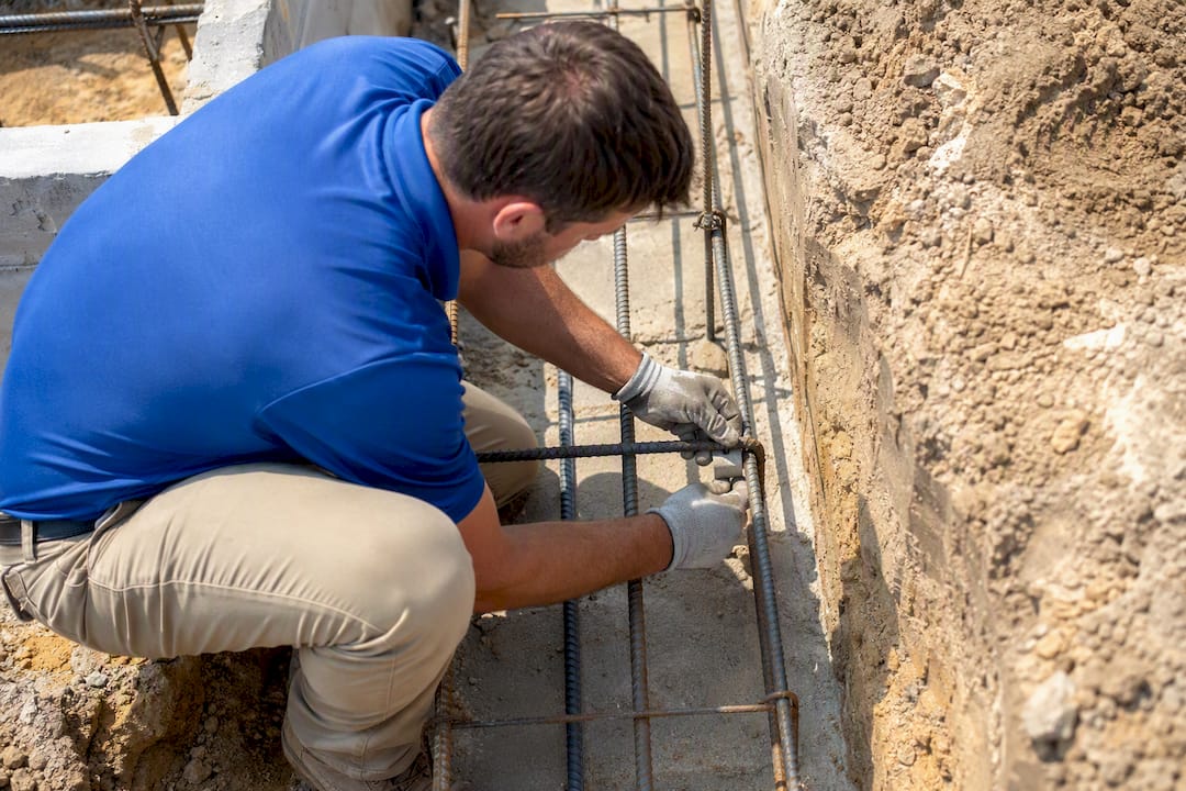
Continuous footings in Seismic Design Categories D0 through D2 need two continuous #4 bars, one near the top and one near the bottom, per IRC Section R403.1.3. That is the prescriptive baseline. Everything else, from bar spacing in stem walls to cover depth against earth, builds off that baseline.
If you’re standing on a job site before a pour, here’s what to verify in the next five minutes:
Bar size and count: confirm at least two continuous #4 bars in SDC D0–D2 footings, not spliced short or skipped at corners.
Top and bottom placement: one bar belongs near the top of the footing, one near the bottom. Bars bundled together or sitting on the bottom of the trench fail this immediately.
Cover before concrete lands: measure clearance with a cover gauge or tape, not by eye. We’ll get into exact numbers shortly.
These minimums come from the International Residential Code, and you can cross-reference the full text through UpCodes’ IRC viewer or your local jurisdiction’s adopted edition. Knowing the code section number matters less than knowing what an inspector should physically see in the trench.
Key Takeaways
Foundation rebar requirements center on three numbers: two continuous #4 bars in SDC D0–D2 footings, 3 inches of cover against earth, and a lap gap no wider than one-fifth the splice length or 6 inches.
Point | Details |
Seismic footings need continuous steel | SDC D0–D2 requires two continuous #4 bars, one near top and one near bottom of the footing. |
Cover depth depends on exposure | Use 3 inches against earth, 1½–2 inches for removable forms, and 3/4 inch for protected interior concrete. |
Wall reinforcement scales with height | Walls over 8 feet or with unbalanced backfill typically need added horizontal and vertical bars per Table R404.1.3.2. |
Congestion undermines strength | Oversized bar counts can block vibrator access and cause honeycombing, so favor fewer, larger bars in tight zones. |
Trinity Home Inspections verifies placement | Trinity documents bar size, cover, and splice details with same-day photo reports before concrete covers the evidence. |
Foundation Rebar Requirements: The Prescriptive Path vs. Engineered Design
Most residential footings in the country never see an engineer’s stamp, and that’s by design. The IRC built a prescriptive path specifically so builders in stable soil conditions with typical loads could skip a structural engineer and follow standardized tables instead. Section R403.1.3 and the adjoining Table R403.1 spell out footing width, thickness, and reinforcement based on soil bearing capacity and the number of stories supported.
Here’s where people get tripped up: the prescriptive tables assume specific soil bearing values, typically 1,500 to 4,000 pounds per square foot depending on soil classification. If the geotechnical report on a project comes back below those assumptions, or if no soil test was performed and the site shows visible signs of poor bearing (soft clay, fill dirt, organic material), the prescriptive path no longer applies. At that point, you need an engineer to size the footing and specify reinforcement directly.
Seismic Design Category is the other trigger that changes everything. In SDC A, B, and C, plain concrete footings without any reinforcement can be code-compliant under the right table conditions. Once a site falls into SDC D0, D1, or D2, the IRC mandates continuous reinforcement in every continuous footing regardless of soil bearing capacity, because the seismic categories reflect a meaningfully higher probability of ground shaking that plain concrete simply cannot handle in tension.
Minimum yield strength for that reinforcing steel is 40,000 psi (Grade 40) in the prescriptive tables, though most suppliers now stock Grade 60 as their standard bar, which exceeds the code floor without issue.
Use this quick decision checklist to figure out whether the prescriptive path applies to a given footing:
Confirm the Seismic Design Category for the site. Your local building department or a geotechnical report will state it directly, and it’s often stamped on the permit set.
Check the soil bearing assumption against Table R403.1. If the project has no soil report and the site looks questionable, don’t guess. Flag it.
Verify wall and footing geometry matches what the table assumes: footing width, thickness, and the number of stories bearing on it.
Confirm SDC status forces reinforcement. In D0–D2, the two continuous #4 bars are mandatory even if the soil table would otherwise allow plain concrete elsewhere in the same jurisdiction.
When any assumption fails, require engineered drawings. A stamped foundation plan overrides the prescriptive table every time.
This isn’t a formality. A footing sized off the wrong table row, or reinforced as if it were in SDC B when the site is actually D1, is one of the more common paper errors that shows up during resale inspections years later.
Foundation Wall Reinforcement Under IRC Table R404.1.3.2
Footings get most of the attention, but the stem wall or basement wall above it carries its own reinforcement rules, and they’re driven by height and backfill rather than seismic category alone. IRC Table R404.1.3.2 sets horizontal minimums that scale with wall height.
For concrete foundation walls up to 8 feet tall, the table typically calls for one No. 4 bar within 12 inches of the top of the wall and a second No. 4 bar near mid-height. Walls that exceed a certain height typically require additional horizontal reinforcement bars with spacing adjusted to thirds of the wall height instead of just a single mid-height line. These are table minimums, not the last word. Actual spacing depends on wall thickness, backfill height, and the specific unbalanced fill condition on that side of the foundation.
Vertical reinforcement is often less visually obvious than horizontal bars, and becomes mandatory when unbalanced backfill height reaches levels specified by code, indicating significantly higher soil on one side compared to the other. A walkout basement with 6 feet of exposed backfill against one wall and a shallow crawlspace on the opposite side is a textbook case where vertical steel isn’t optional.
When you’re checking a formed stem wall or basement wall before the pour, work through this short list:
Measure wall height from footing to top plate line, and note whether it exceeds 8 feet.
Check unbalanced backfill on each side separately. Don’t average it. The highest fill point against any single wall segment governs that segment.
Count horizontal bars and confirm placement near top and mid-height (or thirds, on taller walls).
Look for vertical bars tied to the footing dowels, especially on walls backing up to graded slopes.
Photograph before concrete covers it. This is the only evidence anyone has once the wall is poured.
Concrete Cover, Lap Splices, and Bar Grade Standards
Cover depth is where a lot of otherwise correct rebar placement quietly fails inspection, because it’s easy to tie bars at the right size and spacing while letting them sag or shift too close to the earth-formed edge of a trench.
The IRC sets three distinct cover minimums depending on exposure, and they aren’t interchangeable:
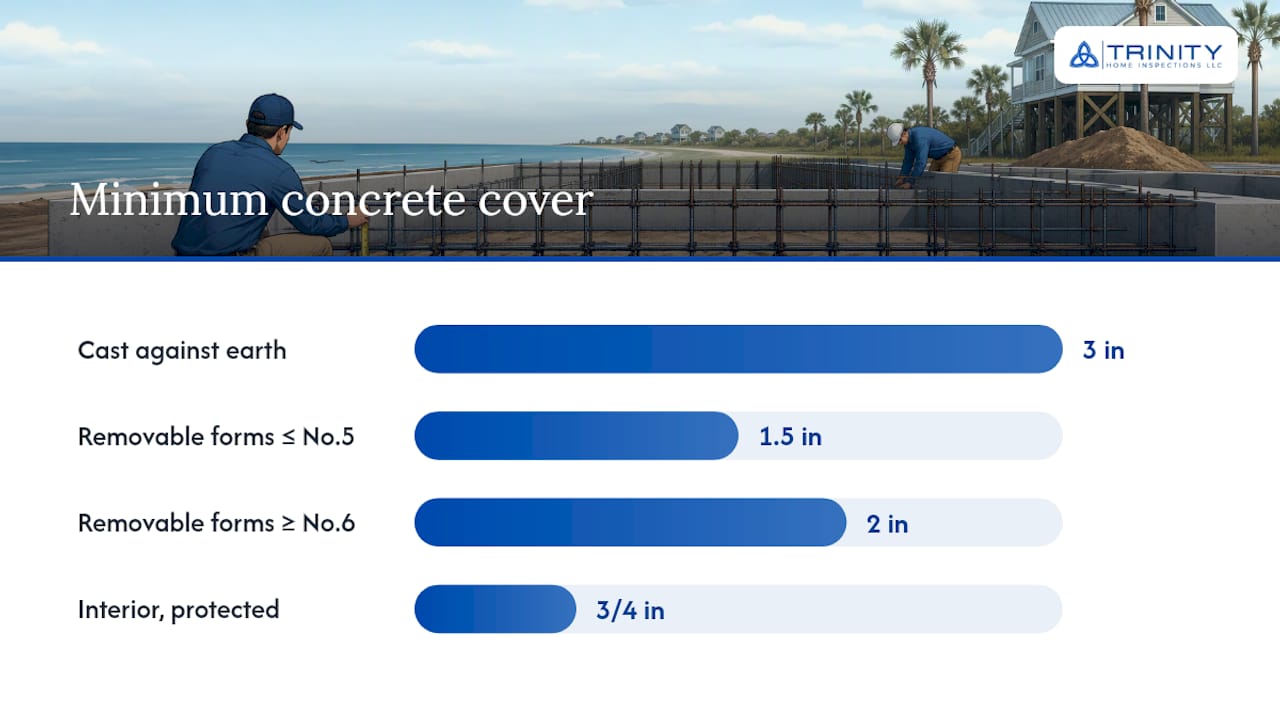
Concrete cast directly against earth: minimum 3 inches of cover, per R403.1.3.5.3. This is the number that governs most footing pours, since footings are almost always formed against the trench wall rather than removable forms.
Removable forms exposed to weather: 1½ inches for No. 5 bars and smaller, 2 inches for No. 6 and larger.
Interior, protected concrete: a minimum of 3/4 inch, the tightest allowance in the table since there’s no soil moisture or freeze-thaw exposure to guard against.
Lap splices are the second detail worth slowing down for. Where two bars overlap to create continuous reinforcement, code limits how far apart those parallel bars can drift within the splice. Per IRC guidance, the gap between lapped bars cannot exceed the smaller of one-fifth the lap length or 6 inches. A lap that looks continuous from a distance but has bars splayed 8 inches apart doesn’t actually transfer load the way the detail assumes.
Bar grade matters too, even though it rarely gets discussed on residential sites. Reinforcing steel is typically specified under ASTM A615 for standard deformed bars, with Grade 60 (60,000 psi yield) now the de facto industry standard, well above the 40,000 psi floor the IRC’s prescriptive tables assume.
Pro Tip: Carry a cover gauge, not just a tape measure. A tape tells you the trench is deep enough; a cover gauge confirms the actual distance from the bar surface to the earth face after the cage has settled, which is what the inspector and the code both care about.
Rebar Size, Spacing, and Placement For Common Foundation Types
Choosing between a #4 and a #5 bar usually comes down to load and constructability rather than a hard code mandate, since most prescriptive footing tables specify #4 as the minimum and leave larger sizing to engineered judgment or contractor preference on heavier structures.
Here’s the practical logic experienced crews use:
Default to #4 for standard residential footings meeting prescriptive table conditions. It satisfies the SDC D0–D2 requirement and handles typical one and two-story loads without issue.
Step up to #5 or larger when spacing gets tight or when an engineer’s design calls for higher tensile capacity, such as heavier masonry veneer loads or unusual span conditions.
Favor fewer, larger bars over many small ones in congested zones. Reinforcement detailing works best when larger-diameter bars reduce clutter and leave room for a vibrator head to actually reach the concrete, which matters more for long-term durability than raw bar count.
Detail corners and steps deliberately. Corners need L-shaped bars that tie perpendicular footing runs together, and stepped footings require diagonal bars across each step, not just horizontal continuity through the flat sections. Missing diagonal bars at steps is one of the most common field omissions inspectors flag.
Size dowels into stem walls correctly. A common rule of thumb calls for at least 14 inches of embedment for No. 4 dowels tying the footing to the stem wall above, with hooks meeting standard code dimensions.
Pro Tip: If a rebar cage looks like a jungle gym before the pour, it probably is one. Congestion is a red flag for poor consolidation, not a sign of extra strength. Ask the crew whether a vibrator head can physically pass between bars before concrete shows up.
A Pre-Pour and Post-Pour Rebar Inspection Workflow
A structured walk-through catches problems while they’re still cheap to fix, before concrete locks everything in place.
Verify bar size against the plan set. Confirm #4 or larger matches what the engineered drawings or prescriptive table calls for, not what happened to be on the truck that day.
Check cover chairs and dobies. Bars should sit on proper supports, not on loose dirt clods or bricks, to hold the 3 inch earth cover consistently along the entire run.
Inspect splices and hooks. Confirm lap lengths and the 6 inch (or one-fifth lap length) maximum gap between parallel bars at every splice location.
Confirm dowel lengths into stem walls. Measure actual embedment, not just visible projection above the footing.
Verify form dimensions. Footing width and depth should match the table or engineered plan before anyone calls for concrete.
Watch for bar displacement during the pour. Concrete flow and foot traffic can shift a cage that looked perfect an hour earlier. This is a mandatory hold point on engineered or seismic-critical work.
Confirm adequate consolidation. A vibrator needs physical access between bars; congested cages that trap air pockets create voids around the steel itself.
Document everything after the pour. Photos of the open trench before concrete, tied measurements, and any thermal imaging taken during a later inspection all support the final report if questions come up months later.
Our own foundation inspection checklist walks through this same sequence in more field detail, including what to flag when a footing has already been poured and you’re inspecting after the fact.
Common Rebar Installation Mistakes And How To Fix Them
Congestion and honeycombing show up together more often than not. When bars are packed too tight for a vibrator to reach, concrete can’t consolidate around the steel, leaving voids that surface as honeycombing once forms strip. The fix is usually larger-diameter bars at wider spacing, or a staged pour that gives the crew better vibrator access in sections.
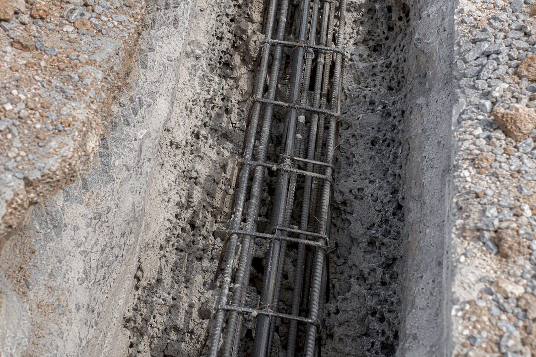
Insufficient cover is the second recurring issue, usually from cages settling onto the trench bottom during the pour rather than from bad tying. Cover chairs at proper intervals solve this before concrete arrives; after the fact, exposed bar requires patching with a corrosion-inhibiting repair mortar, not just a skim coat.
Incorrect splices, missing hooks, or short dowels are the quiet failures nobody notices until an engineer looks closely. Mechanical splices or bar extensions can correct short dowel embedment discovered before the stem wall pours, but catching it at the footing stage is far cheaper than drilling and epoxying dowels into cured concrete later.
Pro Tip: More steel is not automatically better. A cage so dense it blocks consolidation performs worse than a properly spaced, code-minimum cage. Placement and concrete contact around every bar matter more than total bar count.
When Foundation Rebar Requires Engineered Design
Certain site conditions push a project past what the prescriptive tables were built to handle, and no amount of extra bar size fixes a design problem.
Unbalanced backfill exceeding table limits, especially on walkout basements or split-grade lots.
Expansive or compressible soils that the standard bearing-capacity tables never assumed.
High surcharge loads near a foundation wall, such as heavy equipment, retaining structures, or steep site grading.
Any condition where a required soil test comes back outside the prescriptive table’s bearing assumptions, which the IRC addresses directly for sites needing geotechnical evaluation.
Expect an engineer’s deliverables to include a geotechnical report, stamped design drawings, a bar schedule, and, on seismic-sensitive work, special inspection notes. As an inspector, your job is documenting the condition clearly: photos of the backfill height, measured wall dimensions, and the specific table section the site fails to meet.
How Trinity Home Inspections Documents Rebar Findings
Trinity Home Inspections brings InterNACHI certification, FAA drone licensing, and same-day photo and video reports to every foundation-stage inspection we perform across the Gulf Coast.
Pre-pour photos of bar size, placement, and cover before concrete covers the evidence.
Tied measurements of dowel embedment and splice lengths, recorded on-site.
Thermal imaging when moisture or settlement concerns warrant a closer look, included at no extra charge.
Fast, organized reports that give contractors and engineers exactly what they need to act.
Balancing Code Minimums With What The Soil Actually Tells You
Code minimums exist because they work across a huge range of typical conditions, and most residential footings never need to exceed them. But “typical” isn’t universal. On sandy coastal soils with high water tables, or on sites where drainage patterns concentrate moisture against one wall, recommending slightly heavier reinforcement or better cover than the bare minimum isn’t overcaution. It’s matching the fix to the actual soil in front of you rather than the soil the table assumed.
The trick is saying that plainly without turning it into a scare tactic. A good recommendation names the specific site condition, cites the table section it deviates from, and lets the contractor or homeowner make an informed call.
Foundation And New Construction Inspection Services
If you’re a builder, agent, or homeowner who wants a second set of trained eyes on rebar placement before concrete locks it in, Trinity Home Inspections offers pre-pour and new-construction inspections across Baldwin, Mobile, Escambia, Washington, and Monroe counties, with same-day photo and video reports so you’re never waiting days for answers you need before the next pour.
[

What’s included: on-site verification of bar size, cover, and splice placement; tied measurements and photo documentation; free thermal imaging when conditions call for it; and a list of trusted local contractors if corrections are needed before the concrete truck arrives. We also help buyers and builders confirm permit history through our property, deed, and permit search service, so you know the foundation work was actually pulled under permit before you close.
Whether you need a pre-pour walk-through or a full new construction inspection closer to closing, call 251-210-7376 or schedule directly through Trinityinspectionsllc to get a same-day report in hand.
Sources
FAQ
Does A House Foundation Need Rebar?
Most do. Continuous footings in Seismic Design Categories D0 through D2 require two continuous #4 bars by code, and plain concrete is only allowed in lower seismic categories under narrow prescriptive conditions.
Does A 4 Inch Concrete Slab Need Rebar?
A standard 4 inch slab-on-grade often relies on welded wire mesh or fiber reinforcement rather than rebar under prescriptive residential codes, though thicker structural slabs or slabs bearing heavier loads may call for rebar per an engineer’s design.
Do Residential Footings Need Rebar?
Footings in SDC D0–D2 require reinforcement under the IRC, while footings in lower seismic categories may be plain concrete if they meet the soil bearing and geometry assumptions in Table R403.1.
Where Should Rebar Be Placed In A Footing?
Code calls for one continuous #4 bar near the top of the footing and one near the bottom, each held at the proper cover depth with chairs or dobies before the pour.
When Should A Builder Call An Engineer Instead Of Following The Prescriptive Tables?
Call an engineer whenever unbalanced backfill, expansive soil, high surcharge loads, or a soil test outside the table’s bearing assumptions applies, since the prescriptive path no longer covers those conditions.
Recommended